
Build with bodies
Create volumes with primitives, profiles, sweeps and revolves. Combine them with booleans, blends and shells to define the part you need.
Implicit modelling & computational design
Build complex engineering geometry from bodies, fields and parameters. Keep design intent editable as you move from a first concept to automated meshing, CFD and physical simulation.
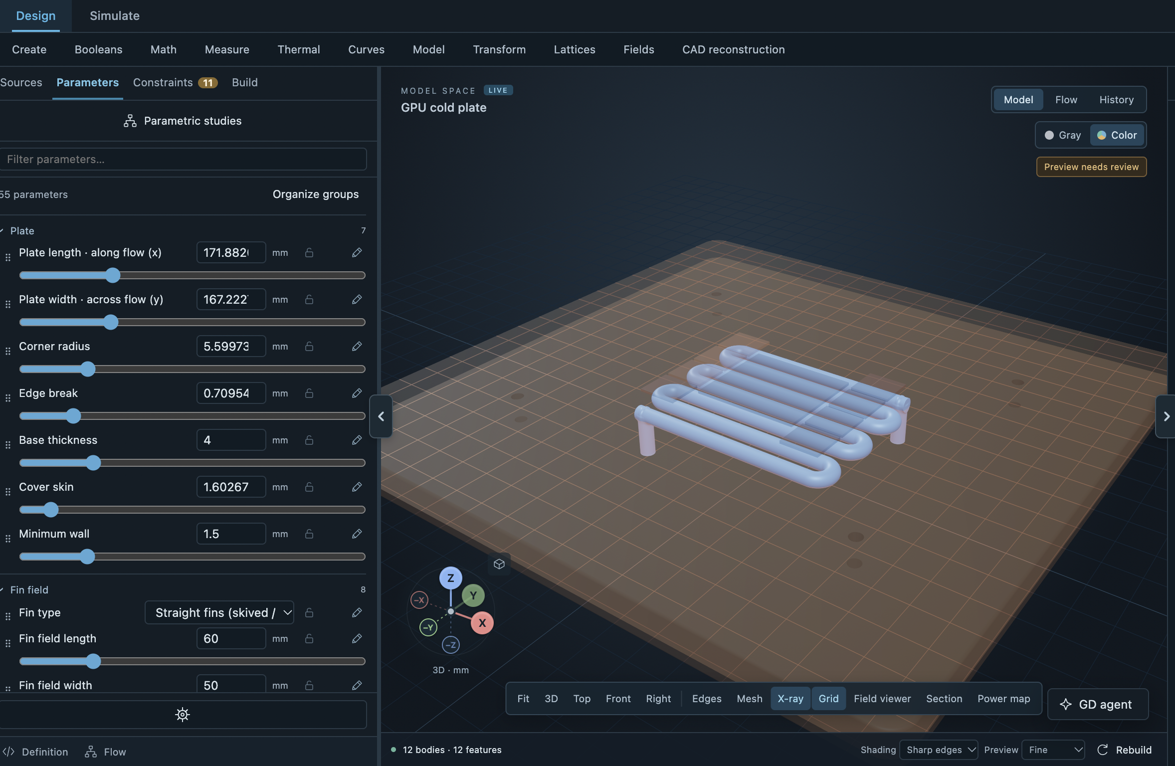
A cold plate model with editable engineering parameters and an internal coolant path.
Geometry as reusable design logic
Implicit geometry represents a volume mathematically. Work with bodies, fields and typed parameters to describe a design, then build on that logic as the engineering changes.
Create volumes with primitives, profiles, sweeps and revolves. Combine them with booleans, blends and shells to define the part you need.
Let thickness, offsets or lattice features vary through space. Use a field to describe a transition instead of editing each feature by hand.
Expose dimensions, counts and constraints as parameters. Revisit the same model, change the inputs and explore a new design variant.
From shells and cooling passages to lattices and graded structures.
Explore the geometry toolsSee the product
Keep the parameters, inspect the internal geometry and see the whole part in context. These examples show the Geometry workspace in Gradient Dynamics Studio.
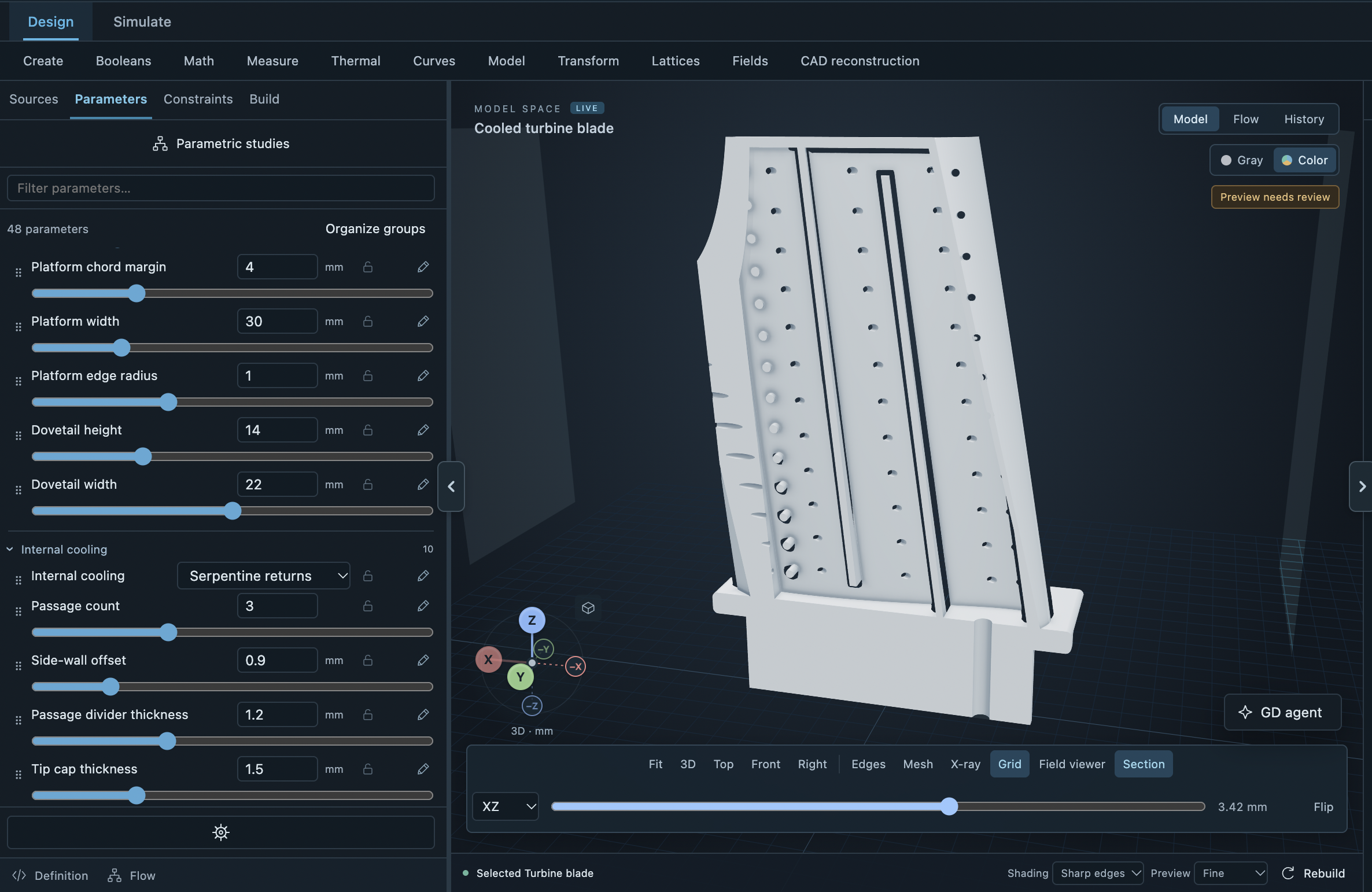
Use sections to inspect internal passages while keeping the parameters that define the surrounding geometry in view.
Play the pump demonstration to see the geometry workspace in action.
Connected to the physics
A useful model carries more than a shape. Keep the physical volumes, units and design parameters that connect geometry to a high-quality CFD mesh and the analysis that follows.
Name the solid and fluid volumes. Preserve the passages, interfaces and dimensions that matter to the engineering problem.
Use STL for a tessellated surface or STEP where the geometry and export route support it. Inspect the exported representation before meshing.
Build the volume mesh for CFD and conjugate heat transfer. In the finite volume method (FVM), those cells are where the solver evaluates the physical fields.
For engineers, developers & AI agents
Engineers can work in Studio. Developers and AI agents can discover geometry operations, work with typed parameters, validate a model and create geometry artifacts through the REST API or Model Context Protocol (MCP).
Work with geometry, parameters, fields and section views in the browser. Keep the model and its engineering context together.
Open StudioDiscover operations, apply typed parameter changes, validate a candidate and create durable geometry artifacts for the next step.
Read the geometry API guideFrequently asked questions
Answers to the practical questions about implicit modelling software, existing CAD, automated meshing and computational design workflows.
Implicit modelling describes a solid through a function of position in space. The body's surface is a level set of that function. Gradient Dynamics combines these bodies with fields and typed parameters, so geometry can be built and changed through reusable design logic.
Bodies, fields and feature graphsBoundary representation, or B-rep, describes a shape through its faces, edges and vertices. An implicit model describes the volume mathematically. That makes fields, repeated structures and boolean combinations natural parts of the design process. Choose the exported representation to suit your downstream CAD, meshing or manufacturing workflow.
Explore implicit modellingYes. The platform supports STEP, STL and 3MF workflows. Supported STEP and 3MF imports can be reconstructed for measured parameter edits. Geometry exports include STL and design JSON, with STEP available for supported geometry and export routes. Keep the editable model alongside the format you deliver downstream.
Import, export and geometry fidelityYes. Available implicit structure families include gyroid, Schwarz P and diamond, with graded gyroid capability. Spatial fields can drive compatible geometry operations, such as thickness and offsets. Use an envelope to define where a structure belongs and inspect its connection to the surrounding geometry.
Lattices and graded structuresClear units, connected passages, appropriate wall thickness and well-defined physical regions are a strong starting point. Preserve the small gaps and features the analysis needs, inspect the geometry, then select mesh resolution and refinement for the flow and heat-transfer problem. Automated meshing works best when the engineering intent is explicit.
Geometry preparation for meshingGeometry defines the physical domain; a volume mesh divides that domain into the cells used by a finite volume solver. In Gradient Dynamics, the geometry workflow feeds automated meshing and CFD or conjugate heat transfer analysis. Keep the named fluid and solid volumes needed by the chosen simulation workflow.
Explore Physics SimulationYes. Geometry operations are available through the central REST API and MCP service used by Studio. An agent can discover operation schemas, work with typed parameters, validate a candidate and create geometry artifacts. Developers can use the same interfaces for repeatable computational design and parameter studies.
Geometry through API and MCPYou can use Gradient Dynamics as part of an existing engineering toolchain. Bring in supported geometry, develop parameterised designs and export the representation your next tool needs. Start with a part and a clear modelling or simulation objective to establish the best handoff for your team.
Plan a CAD handoffStart with your engineering problem
Explore Geometry in Studio, or talk to our team about the part, design space or automated workflow you want to build.